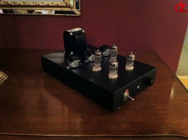
About
This is my DIY build headset class-A tube amplifier that uses an OTL (Output Transformer Less) and MU follower design.
The amplification is around 25dB with the 6CG7 valves, but you can also 6FQ7 for a little higher amplification. The downside of this is however that 6FQ7 doesn’t have an electrostatic screen in the valve design. This can result in some minor audible background noise.
The impedance range of the headsets you may use starts from 50 Ohms – 500 Ohms.
My headset, a Sennheiser HD600 is set to 300 Ohms.
Article
First things first
A schematic, I needed a schematic. So after a few hour of Googling, I’ve discovered this nice little gem from K. Strain.
So after reading it, I’ve discovered some minor issues in the design, not big ones, but just something you could improve.
This improvements were done by Ole W. Saasstad.
While reading this, I had some doubts and questions, so I’ve turned to my trusty little source on the web for amplifiers etc…
The people of UK Vintage Radio and Restoration Forum helped me out allot with this.
Some of the main objections they’ve made where:
- The heater shouldn’t be DC regulated
- Some of the values where wrong
- The start of a simpler drawing
Revision 3
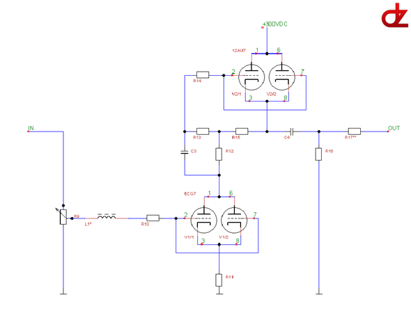
What 3 already? Jip jip, V1 is a design of Kurt Strain and V2 is a design by Saasstad.
The amplifier uses 2×2 parallel switched valves. The 6CG7 is the starting point and the input sound is amplified by 25dB and then the 12AU7 gives you an extra amplification of 30%
Both sides are set up to work in parallel of each other to minimize the background noise. By doing this we achieve a zero-global feedback amplifier with an OTL design of great quality.
But you can also use this design as a good pre-amp, just change the output from a jack socket to RCA jacks (don’t also forget to exclude the end resistors!).
So in the end you have high amplification circuit with a low output impedance and inverted stages who on their turn have a really good PSRR factor and a low non-linear disturbance.
A side note is that this MU-follower will clip when the amplifier is being “pushed”, this effect will give a rich spectrum of even and uneven harmonic sound!
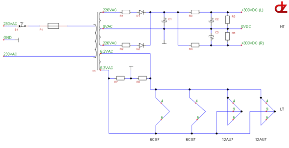
Design
Power supply
Amplifier
Part list
Power supply
- R1, R2 = 47R/1W
- R3, R4 = 220R/1W
- R5, R6 = 100K/3W of 220K/3W (bleeder resistor)
- R7, R8 = 100R/1W
- C1, C2, C3 = 220uF/450V (ELCO, snap in)
- D1, D2 = BY500-1000 Diode
- T1 = Hammond classic HV transformer (H370AX)
- F1 = Fuse slow of 2.5A
Amplifier
- L1* = Optional ferrite core
- R9 = 100K Log (ALPS, Stereo)
- R10, R14 = 100R/1W
- R11 = 51,7R/0,6W of 52R/1W
- R12 = 5,6K/2W
- R13 = 1M/1W
- R15 = 90,9R/0,6W of 91R/1W
- R16 = 22K/1W
- R17** = 50R/1W – 100R/1W (Use only when you have a 32 Ohms headphones)
- C3 = 1uF/450V (film capacitor polypropeen)
- C4 = 10uF/450V (film capacitor polypropeen)
- V1, V3 = 6CG7 (BA-9 socket)
- V2, V4 = 12AU7 (BA-9 socket)